Riccardo Loggini
The D3D12 Pipeline State Object
Table of Contents
Why talking about the PSO
The Pipeline State Object (PSO) is used to describe how the graphics/compute pipeline will behave in every Pipeline Stage when we are going to render/dispatch something.
We can define behavior of both programmable and fixed pipeline stages, by linking compiler shader code and setting a multitude of variable values along the way. Other settings will be available to change behavior of in-between stages, such as viewport and scissor rect, from a command list instead. The PSO definition will also incorporate the definition of a Root Signature, which is used to define the resources types (and their details) available during execution of the pipeline (e.g. textures exposed to be sampled in pixel shader code).
What is The PSO
The PSO is an object that represents the settings for our graphics device (GPU) in order to draw or dispatch something.
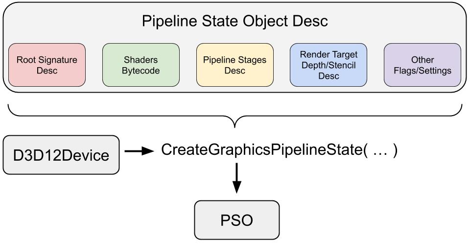
Brief description of its components purposes follows:
-
Shader bytecode: shader code is first compiled and then translated in binary blob data that will serve as an input for the PSO, a process described in the next section.
- Vertex format input layout: definition of how vertex data is composed when passed to the Input assembler stage.
A definition in C++ code will correspond to a struct format in HLSL vertex shader code.
Starting from Vertex Shader side, which is the simplest between the two end points, we are gonna have a struct definition at the start of our shader E.g.struct VertexPosColor { float3 Position : POSITION; float3 Color : COLOR; }; //Used as VertexShaderOutput main(VertexPosColor IN) { … }Each element is in the form of: <type> <name> : <Value Semantic>
For the C++ counterpart, we have:// Create the vertex input layout D3D12_INPUT_ELEMENT_DESC inputLayout[] = { { "POSITION", 0, DXGI_FORMAT_R32G32B32_FLOAT, 0, D3D12_APPEND_ALIGNED_ELEMENT, D3D12_INPUT_CLASSIFICATION_PER_VERTEX_DATA, 0 }, { "COLOR", 0, DXGI_FORMAT_R32G32B32_FLOAT, 0, D3D12_APPEND_ALIGNED_ELEMENT, D3D12_INPUT_CLASSIFICATION_PER_VERTEX_DATA, 0 }, };Which is a vector of D3D12_INPUT_ELEMENT_DESC defining in detail each element of the per-vertex data that will arrive as input to the vertex shader through input assembler.
Value Semantics are specific keywords used to convey data between pipeline stages (e.g. defining output from vertex shader that will be read as input in hull shader when tessellation is active). They will be especially important for fixed pipeline stages to recognise the data that has to be handled (e.g. POSITION in vertex shader output will be essential for the rasterizer stage to properly handle geometry).
Semantics are required on all variables passed between shader stages.
Names can be completely arbitrary so the programmer can set its own flavours.
System Value Semantics There are certain names however, that are already defined with relative data type and can be used in shaders, two examples are POSITION and COLOR (float4).
The series of defined names will be different between pipeline stages, because the input type is also different (e.g. per-vertex data in vertex shader vs. per-pixel data of pixel shader). Full list of already defined semantics is available in the official documentation.
(SV_) available from DX10, are reserved semantics that have been consequently added. Some of them are new and some of them represent older ones. An example is SV_Position which is used by the rasterizer stage. These variables can be input or output of a shader, depending on the shader type and the purpose of the semantic. For example, SV_PrimitiveID indicates the ID of the primitive that is currently being worked on the pipeline, and this value will be invalid in vertex shader, because a vertex can correspond to multiple primitives (e.g. triangles or patches if tessellation is enabled).
There is a defined mapping for certain system semantics from DX9 to DX10 and beyond, e.g. COLOR is treated as SV_Target and POSITION is treated as SV_Position.
For more information, visit value semantics official documentation. -
Primitive topology type (point, line, triangle, or patch) specifies how the input assembler needs to interpret vertex data in order to generate 3D geometry along the pipeline. In D3D12 we can generate either points, lines, triangles or patches (closed geometry that includes more than 3 vertices).
In the PSO this is set using D3D12_PRIMITIVE_TOPOLOGY_TYPE enumeration but it has to be noted that, for each one of those types, there are a set of modes stating how to generate such geometry. This specification is made outside the PSO and described in “In-Command List Settings” chapter below. - Blend state settings are used in the output merger, after the pixel shader, when we define how the just rendered pixel should blend with the content already present in the render target we are writing into. This operation happens just after the depth and stencil tests took place in the output merger.
Blend settings are stated with a D3D12_BLEND_DESC structure, containing:- AlphaToCoverageEnable: option for multisample render targets, useful in cases like rendering foliage, we can use the alpha value of each sample in AND operation with the sample coverage of pixel shader to determine what sample to write into. More details in official documentation.
- IndependentBlendEnable: if set to false, only the first render target (index 0) will be considered for blending. If true also index 1 to 7 will be considered.
- An array of 8 D3D12_RENDER_TARGET_BLEND_DESC , and in D3D12 we can write up to 8 render targets simultaneously. Each one of them has the classic settings present in previous versions of D3D: they define how color computed by pixel shader (Source) should blend with the color already present in the corresponding pixel of the render target (Destination).
Each blend description let us set an operation for Final Color (FC) and one for Final Alpha (FA) separately:$$\begin{matrix} (FC)=(SC)(X)(SBF)(+)(DC)(X)(DBF) \\ (FA)=(SA)(SBF)(+)(DA)(DBF) \end{matrix}$$Where:
(SC) and (DC) are Source and Destination Color (the first from pixel shader result and the second from the already existing value in render target)
(X) is vector cross product operation
(SBF) and (DBF) Source and Destination Blend Factors, two D3D12_BLEND enum values that will alter contribution of source and destination values for the final result.
(+) is a logic operation among the possible from D3D12_LOGIC_OP entries
(for more info visit Braynzar Soft)
Lastly, we also have the possibility to just blend specific channels among R, G, B and A selected with RenderTargetWriteMask that takes an entry from D3D12_COLOR_WRITE_ENABLE enumeration.For more information, refer to output merger official documentation
- Rasterizer state configures the fixed-pipeline stage that transforms per-vertex data of our geometry in normalised device coordinates (NDC) space and generates per-pixel data in screen-space, to be an input for the pixel shader. Luckily for us, programmer’s job is to feed rasterizer with clip-space coordinates data (obtained by applying projection transform to view-space coords) then the rasterizer will perform clipping, then transform to NDC space, then rasterize and output coordinates in screen-space.
Rasterizer stage will always perform Clipping operation, z-divide to provide perspective(incoming vertex position is assumed to be in homogeneous clip-space), Viewport transformation, and depth-bias, all this before performing the actual rasterization of geometry. Optionally it will determine how to invoke the pixel shader if one is bound to the PSO. Clipping operation cuts off every shape that relies outside the view frustum, as conceptually invisible to the viewer.
Coordinate transformations happening in the rasterizer stage are very well described in this youtube video. Parameters for the rasterizer are set in a D3D12_RASTERIZER_DESC struct, which can mainly set:- Geometry culling: discard polygons that have an orientation we don’t need (e.g. facing opposite to the camera) in this way rasterizer will perform less operations and the whole render process will be faster.
- Depth Bias settings: will change the final depth value assigned for each pixel in order to avoid z-fighting artifacts such as depth acne, when we have multiple surfaces drawn one on top of the other with the same depth (e.g. bullet and blood decals drawn onto a wall).
These settings will generate a float value “Bias” that will be added to each vertex’s z coordinate (in NDC-space) before being rasterized, and the bias will be applied to each vertex of a single polygon will be the same. With default settings, polygons with higher z value will be drawn in front of polygons with smaller z values.
The formula to calculate depth bias changes based on depth buffer’s internal format. Just to list the easiest case, when format is UNORM (evenly spaced floating point from 0 to 1) the bias gets calculated by:
Bias = (float)DepthBias * r + SlopeScaledDepthBias * MaxDepthSlope;
Where, thanks to some depth-bias Vulkan documentation, we can briefly explain the quantities: the scope of the formula is allowing us to set a bias value which also depends on the current inclination the polygon has respect to the view point, since a static depth-bias might not solve all the artifacts. - r : the minimum representable value > 0 in the currently bound depth-buffer format converted to float32 (for fixed point depth data format this is constant).
- DepthBias: scalar factor that controls the constant value added to the depth of each fragment, this factor weights the influence that r has on the final value.
We get to specify this value as input. - MaxDepth Slope: m = max(abs(delta z / delta x), abs(delta z / delta y))
represents the maximum depth slope of the current polygon being rendered (maximum between increment of z over increment of x and y for any point in the shape). This is given by the rasterizer stage. - SlopeScaledDepthBias: scalar factor that controls the influence of MaxDepthSlope over the final bias value. We get to specify this value as input.
- MultiSample Anti-Aliasing settings: a set of parameters to configure the rasterizer to apply a multisample anti-aliasing algorithm on bound multisample render targets. This is one of the most effective “smoothing edges” techniques that can help visual result at lower resolution but it is usually quite expensive in frame time and multisample render targets need to be bound just to use this feature.
- Depth-stencil state: configurable through D3D12_DEPTH_STENCIL_DESC struct, it is made to tell the output-merger stage how to perform depth-stencil test, which determines whether or not a computed pixel should still be considered to replace the current value in the bound render target or not, by comparing:
- depth value: if the associated depth value of the pixel we want to write is greater than the associated depth value of the pixel we are going to replace, depth test will pass and our value will replace the existing one, because considered closer to the camera. Additionally, with depth-write mode, the bound depth-stencil buffer will be also updated with the new depth value.
- stencil mask: if our pixel is included in the area of allowance defined by a pixel mask, the stencil test will pass and our pixel value will be considered.
-
Number of render targets and render target formats
-
Depth-stencil format data format for the bound depth-stencil buffer
-
Multisample description describes multisample details for the currently bound render targets with DXGI_SAMPLE_DESC (and render targets must also be created with multisampling enabled)
-
Stream output buffer description configures the stream output stage of the pipeline trough D3D12_STREAM_OUTPUT_DESC .
Stream output stage is located between geometry and rasterization stages. It allows picking data as output from vertex or geometry shader, and making it available (recirculating it) for a subsequent render pass directly as input in the next vertex shader call.
This comes useful, for example, when we perform some geometry operation in vertex or geometry shader and the result to be also used for the next frame, as it happens with rendering of particles. This process will be much faster than store that data in a standalone buffer and reuploading it to GPU for the subsequent pass. - Root signature describes the set of resources (e.g. textures) available in each programmable stage. Since this topic is quite broad, a better description is done in my full standalone article about the root signature.
How To Create the PSO in code
All the different structs describing the various parts of the PSO will serve to create the so called Pipeline State Description object of type D3D12_GRAPHICS_PIPELINE_STATE_DESC. From that, the PSO object is obtained by calling device->CreateGraphicsPipelineState(...) method.
Thankfully, the helper library D3DX12 (available only on GitHub) will provide some helper structs to facilitate this whole process and make it less verbose, by providing another way to create the PSO.
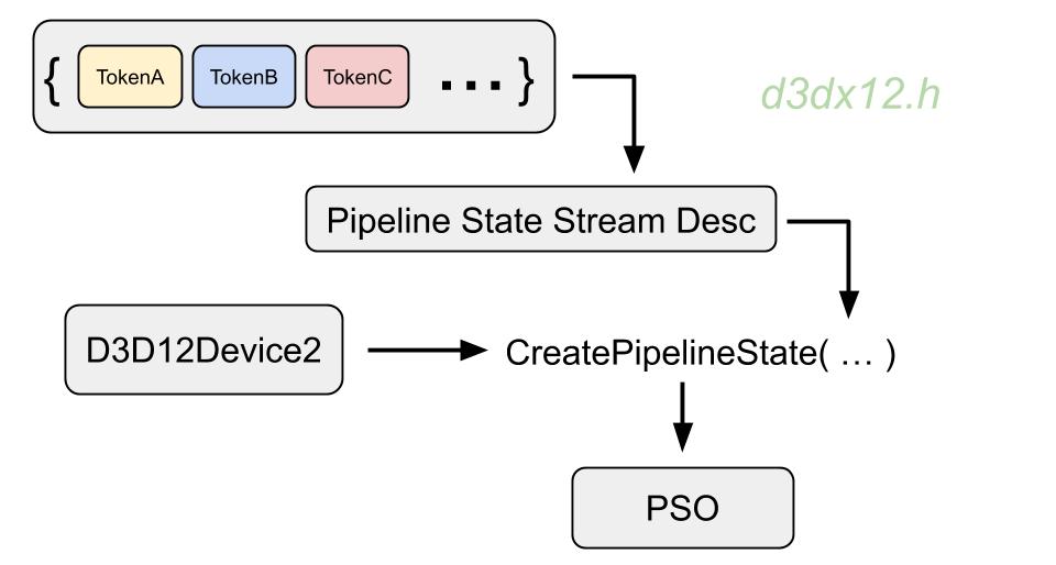
This alternative way will use a D3D12_PIPELINE_STATE_STREAM_DESC type instead of the default PSO description object.
We are also going to need to use an ID3D12Device2 interface type of device.
We start by defining an object type called Pipeline State Stream, a struct made out of Tokens:
struct PipelineStateStream{
CD3DX12_PIPELINE_STATE_STREAM_ROOT_SIGNATURE pRootSignature;
CD3DX12_PIPELINE_STATE_STREAM_INPUT_LAYOUT InputLayout;
CD3DX12_PIPELINE_STATE_STREAM_PRIMITIVE_TOPOLOGY PrimitiveTopologyType;
CD3DX12_PIPELINE_STATE_STREAM_VS VS;
CD3DX12_PIPELINE_STATE_STREAM_PS PS;
CD3DX12_PIPELINE_STATE_STREAM_DEPTH_STENCIL_FORMAT DSVFormat;
CD3DX12_PIPELINE_STATE_STREAM_RENDER_TARGET_FORMATS RTVFormats;
} pipelineStateStream;
Each of those tokens represents an input data for the PSO description, from those described before. There are actually more tokens available, and the number will grow with the expansion of D3D12 features. A full list of tokens is available in the microsoft documentation website.
To define a pipeline state stream object, only a subset of tokens is required: for all the parameters that we don’t specify, the pipeline state stream will assign a default value. That is why we can select any number of tokens for our state stream, still the default PSO state is not enough to make the system work by itself: some components such as the vertex shader, are always needed. The order in which we declare tokens is not important.
After our pipeline state stream object type is defined, we create an object of that type and we fill all the fields with our data:
pipelineStateStream.pRootSignature = m_RootSignature.Get();
pipelineStateStream.InputLayout = { inputLayout, _countof(inputLayout) };
pipelineStateStream.PrimitiveTopologyType = D3D12_PRIMITIVE_TOPOLOGY_TYPE_TRIANGLE;
pipelineStateStream.VS = CD3DX12_SHADER_BYTECODE(vertexShaderBlob.Get());
pipelineStateStream.PS = CD3DX12_SHADER_BYTECODE(pixelShaderBlob.Get());
pipelineStateStream.DSVFormat = DXGI_FORMAT_D32_FLOAT;
pipelineStateStream.RTVFormats = rtvFormats;
With the pipeline state stream description complete, we can now create the PSO object with it, of type ID3D12PipelineState, from the device with CreatePipelineState method:
D3D12_PIPELINE_STATE_STREAM_DESC pipelineStateStreamDesc = {
sizeof(PipelineStateStream), &pipelineStateStream
};
ThrowIfFailed(device->CreatePipelineState(&pipelineStateStreamDesc, IID_PPV_ARGS(&m_PipelineState)));
Note: When we need to change one of the attributes of the PSO, for example changing pixel shader the next frame, we are going to need to recreate the PSO object.
Shaders Bytecode Generation
The PSO description contains D3D12_SHADER_BYTECODE fields for vertex, hull, domain, geometry and pixel shaders. This compiled shader data in binary form is obtained with the following steps:
-
Starting from HLSL code of our shader in a file MyShader.hlsl, we can generate the corresponding Compiled Shader Object (.cso). This object can be generated off-line or at runtime. We of course want to generate most of our compiled shader objects before running the application as much as possible for speed purposes.
-
Off-line compiling is done by using the standalone shader compiler executable FXC.exe that is included with the D3D12 SDK, with a command line like:
fxc /T ps_5_1 /Fo PixelShader1.cso PixelShader1.hlslWhere ps_5_1 is the target profile (pixel shader model 5.1) followed by output file and input file. We can also specify additional flags like if to use debug information. This file can be loaded and automatically converted to binary code by using the function D3DReadFileToBlob.
Off-line compiling can be also done at compile time: Visual Studio can be configured to use the Effect Compiler Tool FXC.exe to automatically compile every file found in the solution that has extension “.hlsl” to a compiled shader object file “.cso”, that can be loaded in binary blob format at runtime by callingReadData(“MyShader.cso”)from a BasicReader object.
There is also the possibility to compile shaders and store the binary blob on byte array variables defined in header files. -
Runtime compiling is done calling D3DCompileFromFile function that receives a path to the .hlsl file and returns the corresponding compiled binary blob directly.
Note: A real case scenario includes a system that stores the compiled shader’s binary blob in permanent memory, so that we just need to load it and link it to the PSO.
In-Command List Settings
These additional settings are controlled by calling methods on the Command List, from a ID3D12GraphicsCommandList object (as described in the official documentation), rather than the PSO. This is because we can modify them on the fly without recreate the PSO, and use this last one for multiple command lists that do different tasks. For each of these settings that we do not specify, a default value will be assigned.
-
Vertex and Index buffers: the number and view interfaces of the vertex and index buffer that we want to bind as input for the input assembler in the current drawing pass.
This is done by callingIASetVertexBuffersandIASetIndexBuffersmethods. -
Stream output buffers: number and view interfaces of buffers that we want to bind for the stream output stage, done by calling
SOSetTargetsmethod. -
Render targets: number and view interfaces of our render targets that we want to write into, done with
OMSetRenderTargetsmethod. -
Descriptor heaps: number and resource views of the descriptor heaps (that are containers for resource views) that we want to bind for the current command operations, done with
SetDescriptorHeapsmethod. -
Shader parameters: constant buffers, read-write buffers, and read-write textures, done with all
SetGraphicsRootandSetComputeRootmethods. - Viewports: viewports define the 2D area of interest for our submitted geometry among the whole render target surface. They will scale dimensions and apply translations to the render geometry among the render target space, at our disposal.
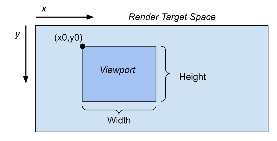 $X0,Y0, width,height,MinZ,MaxZ$ are set by using a D3D12_VIEWPORT structure.
MinZ and MaxZ indicate the render target’s depth range in which our geometry will be drawn. To leave the behavior unchanged, that range will be from 0 to 1. The needed operations to apply those values are made at the beginning of the rasterization stage by the system (so we don’t need to take care of it!).
For the sake of knowledge, that is achieved by multiplying position data for the following matrix (Viewport transform):$$\left[ \begin{matrix} dw Width/2 & 0 & 0 & 0 \\ 0 & -dw Height/2 & 0 & 0 \\ 0 & 0 & dv MaxZ-dv MinZ & 0 \\ dw X0+dw Width/2 & dw Height/2+dw Y0 & dv MinZ & 1 \end{matrix} \right] $$wherere $dv$ and $dw$ are render target’s units for width and height.
Note: We can obtain special effects, such as render everything in foreground (like flat objects for UI purposes) by setting MinZ=MaxZ=0 OR render everything in background (like a skydome) by setting MinZ=MaxZ=1.
Still, in most cases we want the range to cover the whole depth buffer spectrum (from 0 to 1) for our 3D models. -
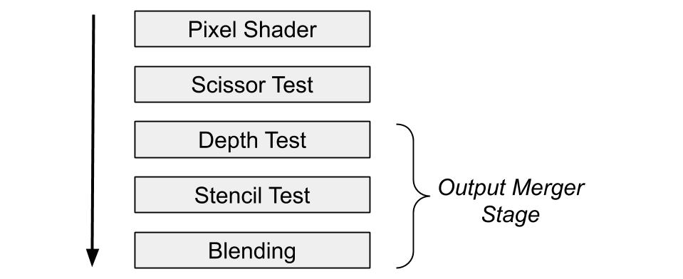
Scissor rectangles define areas inside the render target to consider valid for the output merger stage. This data is used for the Scissor Test, that will discard every pixel, computed by the pixel shader, that relies outside the bounds defined in scissor rectangles. It is notified to the command list by calling the
RSSetScissorRectsmethod.
-
Constant blend factor sets the scalar value of the factor that will be optionally used during Blending and decided in the PSO Blend State description (when D3D12_BLEND::D3D12_BLEND_BLEND_FACTOR and/or D3D12_BLEND_INV_BLEND_FACTOR are used in the blending formulas). This value is set from the command list using the
OMSetBlendFactormethod. -
Stencil reference value is the default scalar value used when the stencil mode in the PSO is set to D3D12_STENCIL_OP::D3D12_STENCIL_OP_REPLACE.
Shader Specified Stencil Reference Value is a feature of D3D11.1 and 12 that allows to define a default stencil scalar value to use for the current draw, and that to be editable in a granular per-pixel manner inside the pixel shader, referring to the system value semantic SV_StencilRef. This mode will effectively write into the stencil buffer (and then used for the stencil test). The scalar value is set using theOMSetStencilRefmethod from the command list. - Primitive topology and adjacency information: this data is set on the PSO with a D3D_PRIMITIVE_TOPOLOGY enumeration and need to call
commandList->IASetPrimitiveTopology(D3D_PRIMITIVE_TOPOLOGY_TRIANGLELIST);
It specifies what is already declared in PSO under primitive topology type, but now this describes how the input assembler should interpret vertices in the vertex shader for the pipeline to generate the chosen geometry.
To name two of them, when we want to render triangles we can state to pick vertices in groups of three from the vertex buffer (e.g. 0-1-2, 3-4-5) in the way known as Triangle List, or have concatenated geometry by re-using the last two vertices of each triangle to generate the next one (e.g. 0-1-2, 2-1-3) a way known as Triangle Strip.
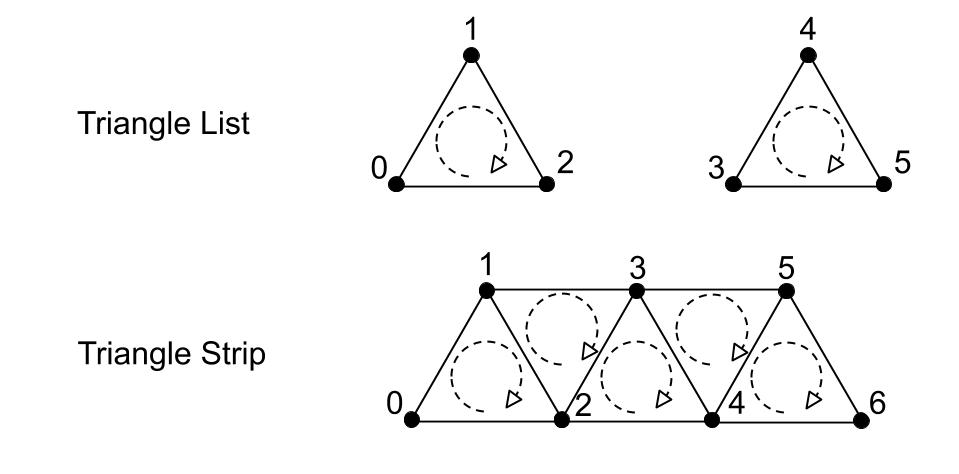 But of course there are many more primitive topology types, for a full list refer to the official documentation on primitive topologies.