Riccardo Loggini
Textures in D3D12 - Part 1
Table of Contents
Why talking about textures
Textures are one of the most important and common components in computer graphics: they are used to map images to geometry and, in a more generalized way, to store data in matrices that is going to be accessed with high frequency by shaders.
When the graphics programmer uses a texture it is important to know what a texture is made of and how they can differentiate between formats.
More than that, there are many tools from D3D12 dedicated to texture handling in proportion to the many usages we can find in real-time graphics.
This is the first of two posts related to textures, you can find the second part here.
Textures are a very broad topic in computer graphics and D3D12, here you will find my humble take on describing the sides that I found most important to know about and that I wanted to learn myself.
Texture Composition
Textures are data used to display images in computer graphics.
A texture is made out of Texels. A texel can be seen as a single-color tile that compose the texture when that is seen as a mosaic.
In a more technical way, we can see the texture as a matrix where at coordinate (x,y) we find a precise texel. Still, with texture there is more depth to that, because we can query (sampling) the color of the texture with normalized axis, so with x and y in range of 0 to 1, and specific filtering will be applied to return the requested color.
With texture we also identify the file that stores such data, which can be of different formats, and formats can contain subresources such as texture mipmaps.
Mips
Mipmaps, or simply Mips, are smaller versions of a texture image, representing different levels of details.
Mip 0 is the original texture, while the next mips are a smaller version of it, where each mip level is half the size of its previous one.
The entire set of mips is called Mipmap Chain.
The number of mips we can generate in an application is arbitrary, but if we half the size of the texture on each level, we are going to have a maximum of log2(n) mips, where n is the bigger between number of pixel in width and height of the texture.
We use mips mainly for two reasons: limiting visual artifacts (aliasing) and for performance reasons.
 Texture aliasing on the left, mipmaps on the right (from Wikipedia).
Mipmaps limit Texture Aliasing, a color noise, in the context of textures, given by a pixel on the screen using the color of the nearest screen-space texel. This produces noise since the color of the pixel should be an interpolation of all the neighbouring texels of the texture that map into it.
Another benefit of mips is texture caching: when the sampling of a texture is frequent, their mip levels can be stored in cache memory, because of smaller size, so sampling operations on them will be faster.
Mips could be automatically generated in D3D11 but now in D3D12 is full responsibility of the programmer to generate them.
We call Mipmapping the process of generating texture mips: starting from the original image, also identified as mip 0, we can obtain mip n+1 by generating an image with the same content but half the size of its previous level.
This recursive operation of texture downscaling, also called Texture Minification, is best done with the use of texture filtering, that will reduce aliasing artifacts.
Mipmap generation works best when the input image is square and width and height are power of two: this because we can always evenly divide such size to create the next mip (down to 1x1 size) and having no issue with the needed filtering operations (more on this later).
We can store pre-processed mips inside the texture file, with a block compressed texture, available with the DDS format (more information in the next section). Loading pre-processed mips will be faster than generating them on application load each time.
In D3D12 a texture is a resource, and mips are identified as subresources.
Taking in consideration an array of textures represented by D3D12_TEX2D_ARRAY_SRV structure (of 3 elements in the example below), the mip levels will follow their original image in the order of subresources.
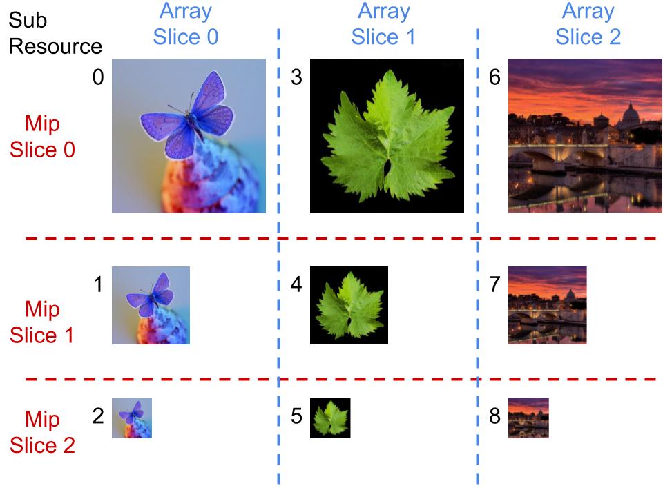
We call Mip Slice all the mips at the same level.
We call Array Slice all the mips belonging to the same texture.
These distinctions are also important when handling cubemaps, where each face will represent an array slice.
Note: A shader-resource view can access any rectangular region of the resource, covering all the subresources inside the rectangle (that can be different mips from different array slices). Something that is not possible with render-target views.
You can read more about texture subresources in the official documentation.
Texture File Formats
A texture can be stored in various file formats, depending on what data we can store, the level of compression and the precision we want to achieve for texels.
Textures are stored in files with a specific layout, usually composed by a header which specifies the characteristics of the data (e.g. pixel format), followed by an array of data for each resource (also called surface) stored in it.
For example, if our files contain mips or cube map faces, then we are going to find multiple surfaces stored in the relative file.
When texture data gets uploaded to the GPU, it needs to be in a format that the GPU can understand. If this is not the case with the original texture, a conversion needs to happen.
Textures are often compressed before getting uploaded to the GPU, at least when talking about games, because they can take up to 8 times less memory by doing it.
-
DDS: Direct Draw Surface format is a Microsoft format for storing uncompressed or compressed (DXTn) textures. Multiple DDS subformats exist corresponding to different versions and the type of data stored.
This format is able to store texture with mipmaps, cubemaps, volume maps and texture arrays.
When using any DDS format, we don’t need to decompress the image before GPU upload, because with this format the data is stored with the exact formats that the GPU needs. This is one of the reasons why it is often handy to convert image formats to DDS before uploading them to GPU, or store them directly in DDS format on the hard drive.
DDS compression types can be many, but the following are the main ones:-
BC1: also known as DXT1, scales the size down to 1:8 or 1:6 when using alpha.
-
BC3: also known as DXT5, scales the size down to 1:4 . This format also differs from BC1 because it supports different alpha (transparency) levels for the image.
There is also a variant called BC3n that was made explicitly to be used with normal maps that would otherwise show noticeable artifacts when compressed. -
BC6H is a lossy block based compression (meaning texels are stored in matrix blocks, convenient for native hardware decompression). It scales the size down to 1:6 and it is commonly used to store HDR textures.
-
-
JPG and PNG: these formats are compressed in a way that is not understandable by GPU processing so they will be required to uncompress pixel data before uploading the corresponding texture data to the GPU.
We usually do not need to uncompress these formats by ourselves, because there are already quite a number of libraries that can perform this operation when loading/storing textures from/to files. More about this in the Updating Content section later on.
JPGs have the advantage that they are of smaller size when both compressed and uncompressed compared to DDS and PNG. Meanwhile PNG performs less compression and can store transparency data. -
BMP: Bitmap image file contains uncompressed or compressed with lossless compression data, which means it will preserve data accuracy but the size will be bigger compared to the other formats.
Texel Formats
Texel format in D3D12 is one of the parameters of D3D12_RESOURCE_DESC structure, named simply “format” and having a type from DXGI_FORMAT enumeration.
There are many and various defined texel formats, but I wanted to briefly focus on a subset that encode their data as sRGB.
sRGB: is a gamma corrected texel format (more info later in the Gamma Correction chapter) and it will store data using more precision for darker values, while compressing brighter values more. This comes useful to reflect human eye sensitivity to colors.
More than that, sRGB is an entire color space defined by ISO standards. More specifications about this can be found in this article by colour-science.org.
All the formats that have the _SRGB modifier will have R, G and B channels stored in Gamma 0.45 (while the A channel will be stored in Gamma 1) so storing channels intensity with applying a power function with exponent 0.45, even though the official sRGB standard defines a slightly different equation (more details about Gamma space later).
Note: The official documentation about DXGI_FORMAT states that sRGB is stored with Gamma of 2.2 but what they really mean is sRGB format stores texel color intensity with an applied Gamma of 1/2.2 which is about 0.45 .
Sampling
Sampling, in a texture context, is the process of retrieving a color value inside the texture domain, by giving texture coordinates as input.
Considering the common 2-Dimensional texture, each coordinate goes inside the range [0,1] (normalized texture space) where (0,0) is the top-left corner while (1,1) is the bottom-right of the texture.
In D3D12 sampling is done using a Sampler object that can be used in shaders and that has to be created and referenced to the root signature.
To use a sampler in shaders, we first need to declare it at the top of the file, along with the other referenced resources.
Texture2D<float4> MyTexture : register( t0 );

SamplerState MySampler : register( s0 );
Then we can use it in a shader by calling functions such as SampleLevel
float4 sampledColor = SrcMip.SampleLevel( MySampler, UVcoords, SrcMipLevel );
Where UVcoords are the normalized space [0,1] x and y coordinates that we want to sample in the image, and SrcMipLevel the mip level we want to sample from.
To be able to use a sampler, we need to define it in the application code by passing it to the root signature beforehand. Samplers can be Static Samplers, where the state is fully defined and immutable and do not count toward the 64 DWORD limit of the root signature. The other possibility is to use a descriptor table (in the root signature) that references a range in a samplers heap. For simplicity purposes here I will illustrate how to instantiate a static sampler.
Note: Static Samplers can be written as part of the root signature in HLSL shader code, more about this in the official documentation.
We start by creating a sampler description object, we can use D3D12_SAMPLER_DESC structure or CD3DX12_STATIC_SAMPLER_DESC structure from the D3DX12 header library containing some helper member functions.
CD3DX12_STATIC_SAMPLER_DESC mySamplerDesc(
0,
D3D12_FILTER_MIN_MAG_MIP_LINEAR,
D3D12_TEXTURE_ADDRESS_MODE_CLAMP,
D3D12_TEXTURE_ADDRESS_MODE_CLAMP,
D3D12_TEXTURE_ADDRESS_MODE_CLAMP );

CD3DX12_VERSIONED_ROOT_SIGNATURE_DESC myRootSignatureDesc(
numRootParameters,
rootParameters, 1, &mySamplerDesc
);

// .. create the root signature, bind to the PSO, etc.
It is enough to reference the static sampler when we are defining the root signature description and we will be ready to use it in shaders. You can read more about root signatures in my previous article about Root Signatures.
A D3D12_SAMPLER_DESC contains a series of parameters that define how the sampler is going to retrieve the color at the given coordinates. The Filter parameter is described in the next section, it defines what happens when we sample an area of the texture that corresponds to multiple texels (e.g. when we apply a size transformation or when we rotate the texture).
Address Mode determines how the texture is sampled outside the space [0,1] in x, y and z (in the case we are handling a third dimension).
There are mainly five different address modes in D3D12.
- Wrap Address Mode will simply consider the fractional part of the UV coordinates we want to sample.
uvCoord = frac(uvCoord)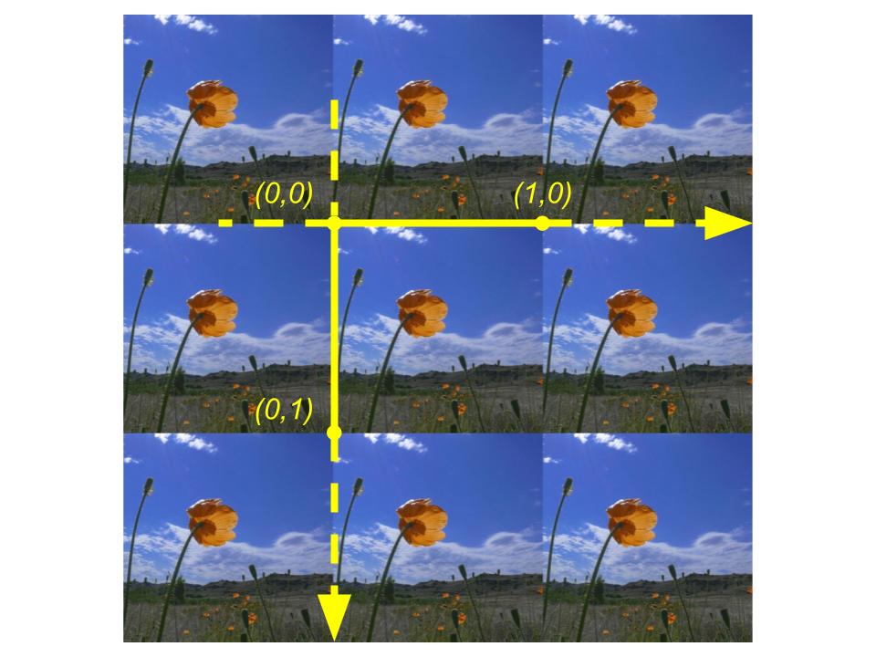
- Mirror Address Mode will act like wrap address mode but it will take one minus the fractional part of an input coordinate if the integer part is odd
if uvCoord is odd then
uvCoord = 1 - frac(uvCoord)
else
uvCoord = frac(uvCoord)
endif
- Clamp Address Mode will return 1 if a UV coordinate is greater than 1, will return 0 if a UV coordinate is less than 0, otherwise no modification will be applied.
if uvCoord > 1 then
uvCoord = 1
else if uvCoord < 0 then
uvCoord = 0
endif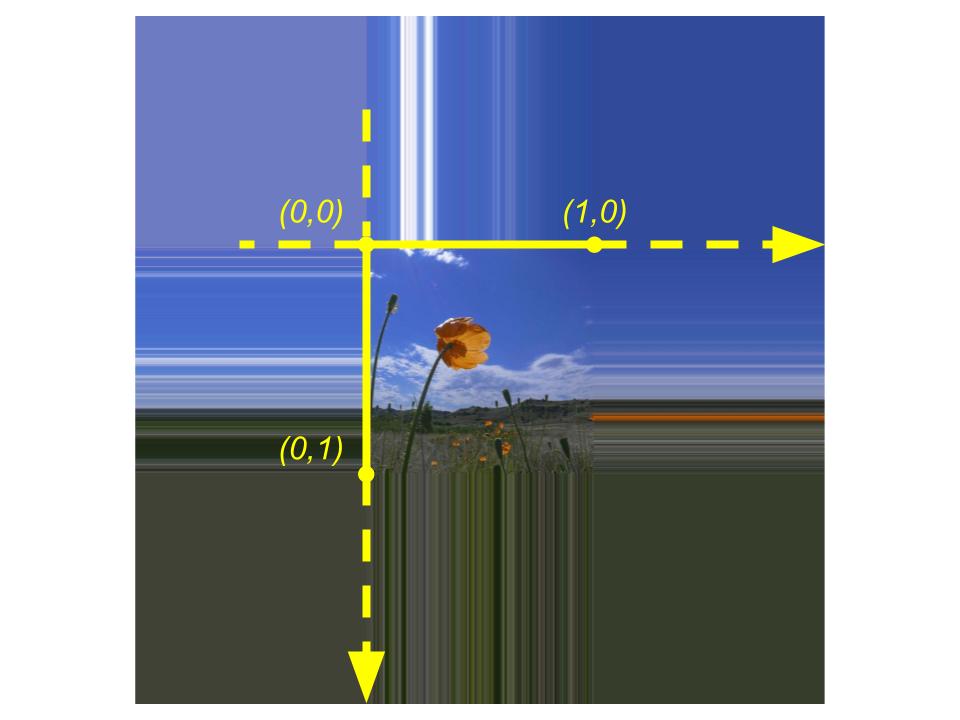
- Border Address Mode will return the selected Border Color specified in the sampler description when sampling with a coordinate outside the range [0,1]
if uvCoord < 0 or uvCoord > 1 then
return borderColor
endif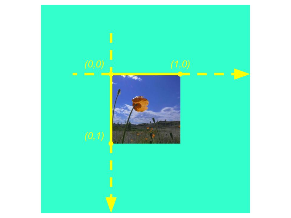
- Mirror Once Address Mode acts like Mirror Address mode for coordinate interval [-1,1] and applies Clamp Address Mode otherwise
if uvCoord < -1 or uvCoord > 1 then
return ClampAddressMode(uvCoord)
else
return MirrorAddressMode(uvCoord)
endif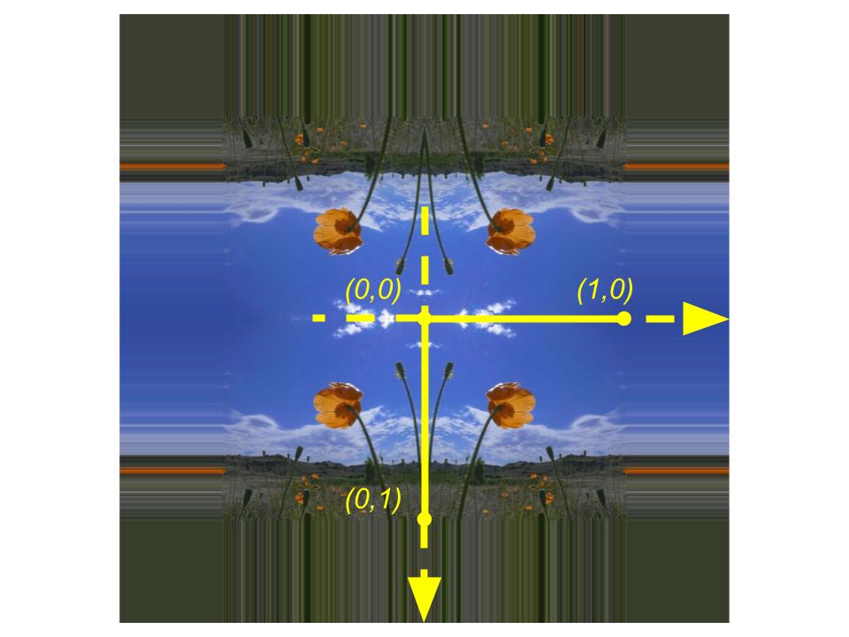
LOD Bias is an offset for each time a mipmap level is specified with the sampling operation (e.g. when we are using SampleLevel function in a shader). This setting turns useful when we want to apply a different level of detail for performance reasons.
Min/Max LOD Clamping can be used to limit the sampling operation to a certain range of mipmap levels. This is another setting useful to help performance but also for mipmap debugging purposes.
Comparison Function is one of the values of D3D12_COMPARISON_FUNC enumeration and it is used when calling functions like SampleCmp and SampleCmpLevelZero in shaders, in order to compare sampled color values. For the most common sampling operations, this setting is not needed.
Sources
-
3DGEP - Part 4 https://www.3dgep.com/learning-directx-12-4/
-
Official D3D Documentation
https://docs.microsoft.com/en-us/windows/win32/direct3ddds/dx-graphics-dds-pguide -
Garage Games - Texture Compression
http://docs.garagegames.com/torque-3d/official/content/documentation/Artist%20Guide/Formats/TextureCompression.html -
Kinematic Soup - Gamma and Linear Space
https://www.kinematicsoup.com/news/2016/6/15/gamma-and-linear-space-what-they-are-how-they-differ -
Handles Pixels - Understanding Gamma Correction
https://handlespixels.wordpress.com/2018/02/06/understanding-gamma-correction/ -
FreeImages.com
https://www.freeimages.com/ -
Colour-Science.org - sRGB Uncertainty
https://www.colour-science.org/posts/the-importance-of-terminology-and-srgb-uncertainty/ -
Cambridge In Colour - Gamma Correction
https://www.cambridgeincolour.com/tutorials/gamma-correction.htm -
Wikipedia - Mipmap aliasing comparison
https://commons.wikimedia.org/wiki/File:Mipmap_Aliasing_Comparison.png -
Wikipedia - Texture Filtering
https://en.wikipedia.org/wiki/Texture_filtering#Linear_mipmap_filtering -
Newcastle University - PS3 Introduction to GCM
https://research.ncl.ac.uk/game/mastersdegree/workshops/ps3introductiontogcm/GCM%20Texturing.pdf -
Florida State University - Image Processing - Gamma Correction https://micro.magnet.fsu.edu/primer/java/digitalimaging/processing/gamma/index.html