Riccardo Loggini
Compute Shaders in D3D12
Table of Contents
Compute Shaders in D3D12
Why Talking About Compute Shaders
Direct Compute has been part of DirectX since version 10. Its usages are multiple, but in general we can use the compute pipeline whenever we want to calculate something without the need of a rasterizer.
This ability to generically adapt to any type of calculus makes the compute pipeline really useful in many areas, not only for real-time applications, but also for many science-related computations. In science, every operation that involves the word "GPGPU" (General Purpose GPU) has some kind of compute shader usage in it: high performance computing, physics simulations, classification, image processing are just to scratch the surface among the multitude of use cases. In a game engine, compute shaders can be used to generate particles, physics, screen-space effects, deferred lighting and volumetric effects.. to name a few!
This post takes a practical and fundamental approach to the use of Direct Compute in DirectX 12 by first describing the available tools and then going through a basic usage in code.
The Compute Pipeline
The compute pipeline was present since DirectX10 and the relative API goes under the name of DirectCompute (something aside from Direct3D). DirectCompute is an API from Microsoft but in the graphics scene we have other products like OpenCL from Khronos Group and CUDA from NVIDIA.
Note: CUDA is both a hardware architecture and a programming language from NVIDIA. A DirectCompute application can run on CUDA hardware.
By using a compute pipeline we can still operate with Direct3D resources and we can use most of the texture features (e.g. cubemaps and mipmaps). Use limitations in this regard will be described later.
Parallel Execution Model
The compute pipeline subdivides work into groups of parallel threads, identified along a three dimensional space (x, y and z), further subdivided in thread groups.
Each thread will execute the instructions given by the compute shader. The parallel code is executed in hardware through warps , groups of usually 32 threads each.
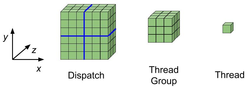
The compute pipeline states the following definitions:
-
Thread Group : 3D grid of threads. Threads in the same group run concurrently. Threads from different groups may run concurrently but this is not handled by hardware and it requires other ways, such as sending multiple parallel dispatch commands.
-
Dispatch : 3D grid of thread groups. We can execute a dispatch command ID3D12GraphicsCommandList::Dispatch from a compute command list indicating the number of thread groups in the x, y and z dimensions.
-
Thread : a single shader invocation. Thread instructions are executed sequentially.
For each thread, the following system value semantics will be available as input to any compute shader:-
SV_GroupID (uint3): the group offset within a single Dispatch call across three dimensions.
-
SV_GroupThreadID (uint3) the thread offset within the group across three dimensions.
-
SV_DispatchThreadID (uint3) the global thread offset within the dispatch call across three dimensions.
SV_DispatchThreadID =(SV_GroupID⋅NumThreadsPerGroup)+SV_GroupThreadID -
SV_GroupIndex (uint) flattened array index version of the SV_GroupThreadID.
SV_GroupIndex = SV_GroupThreadID.z * NumThreadsPerGroup.y *NumThreadsPerGroup.x + SV_GroupThreadID.y*NumThreadsPerGroup.x +
SV_GroupThreadID.x
-
Threads within a group can share memory with Thread Group Shared Memory (TGSM) by defining a variable with groupshared like
groupshared float2 MyArray[16][32];
This memory will persist only for the current Dispatch command and it is of course available for threads belonging to a single group. Using shared memory can slow down performance and it is recommended to execute a read/write once per each TGSM address.
Maximizing Occupancy
When using the compute pipeline we want to maximize Hardware Occupancy , a value that can be defined as:
Hardware Occupancy = num( active warps) / num(max concurrent warps)
where, as stated before, a warp is a group of (usually 32) threads that GPU hardware executes concurrently. All threads in a running warp execute the same set of instructions in the same clock cycle, while different warps are executed independently unless specific synchronization by the Warp Scheduler.
A warp is always run entirely by the GPU: if our computation is using half of the threads in a warp (e.g. thread group not divisible by 32) then the remaining threads will idle and potential parallel computation will be wasted.
We can briefly consider the modern GPU architecture, composed by a number of Streaming Multiprocessors (SM). Each of them contains:
- Shader Registers : the hardware resources used by shader instructions running on our threads.
- Several Caches:
- Shared Memory used by the TSGM defined in the previous chapter.
- Constant Cache to fast broadcast of reads from constant memory.
- Texture Cache to aggregate bandwidth from texture memory.
- L1 Cache to reduce latency to local or global memory.
- Warp Schedulers that will issue instructions to warps that are ready to execute.
- Execution Cores to perform arithmetic operations:
- CUDA Cores : for integer (
INT32CUDA Core), single (FP32CUDA Core) and double floating point (FP64CUDA Core) operations. In hardware a single precision core includes an integer unit and float unit, while double precision float cores are less in number and in standalone location. - Load Store Cores (LT/ST): for shader instructions that involve load or store on global memory.
- Special Function Units (SFU): for single-precision floating-point transcendental functions, used for quickly computing functions like
acos,logandcosh.
- CUDA Cores : for integer (
Follows a streaming multiprocessor scheme of a Fermi architecture gotten from wikipedia.
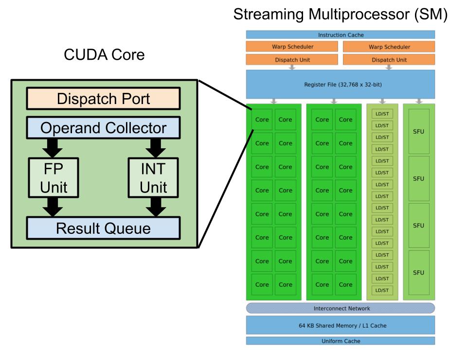
Note: as of writing this post in 2020, the current Nvidia GPU architecture Turing has somewhat changed from Fermi which is from 10 years ago. We have things like concurrent FP and INT execution datapaths, Tensor Cores and RT Cores.\ Still describing all the works behind a GPU goes beyond the scope of this article and you can read more about Fermi Architecture clicking here and also Turing Architecture clicking here.
One or more Thread Groups can run in a single streaming multiprocessor: the number depends on the resource used by each thread group. When we define a thread group we are going to declare:
- Number of threads in the thread group.
- Size of shared memory used by each thread group.
- Number of registers used by each thread group.
Such numbers will be used by the hardware to better allocate as many thread groups as possible per each streaming multiprocessor.
If, for example, the thread group declares 48KB of shared memory and each SM has 64KB of available shared memory, the system will be constraint by it and we will have only a single active thread group per each streaming multiprocessor.
The following table shows a comparison between the most recent Nvidia GPU architectures and their hardware limits:
| Feature | Pascal GP100 | Volta GV100 | Ampere GA100 |
|---|---|---|---|
| # of SM Units | 60 | 84 | 108 |
| Threads per Warp | 32 | ||
| Max Warps per SM | 64 | ||
| Max Threads per SM | 2048 | ||
| Max Thread Blocks per SM | 32 | ||
| 32-bit Registers per SM | 64 K | ||
| Max Registers per Block | 64 K | ||
| Max Registers per Thread | 255 | ||
| Max Threads per Block | 1024 | ||
| Shared Memory Configurations | 64KB | configurable up to 96KB | configurable up to 164KB |
| Max Shared Memory per SM | 64KB | 96KB | 164KB |
| Max Shared Memory per Thread Block | 48KB | 96KB | 160KB |
For a more in-depth spec comparison, reference the article by microway.com and the NVIDIA CUDA Documentation
Note: The number of registers used per thread, and so per shader we are using, will affect occupancy.
It is a good practice to have the number of running thread groups always greater than the number of streaming multiprocessors, especially if we can fit multiple thread groups in a single multiprocessor. In general having:
Num(ThreadGroups / SM) > 2
And consider that a warp can be waiting for some operation happening, and the warp scheduler can run another warp in the meantime.
There are other factors when we talk about optimizing compute shader performance, such as considering Thread or Warp Divergence , GPU Bandwidth , Synchronization and Memory Coalescing , but this goes beyond the scope of this article. You can read more about it in sources like Nvidia DirectCompute Conference Slides (2010).
Unordered Access Resources
An Unordered Access Resource , that can represent a buffer, a texture or a texture array, allows unordered read/write operations from multiple threads concurrently. This means we can perform thread-safe operations on it by using atomic functions. Such resources were introduced in shader model 5 (D3D11) and before that the resources were read-only. Both textures and buffers can be created with unordered access.
They are created using the usual resource creation methods such as ID3D12Device::CreateCommittedResource, but they need to specify the D3D12_RESOURCE_FLAG_ALLOW_UNORDERED_ACCESS flag and cannot be identified as render targets or depth stencil, so they cannot use D3D12_RESOURCE_FLAG_ALLOW_RENDER_TARGET nor the D3D12_RESOURCE_FLAG_ALLOW_DEPTH_STENCIL flags.
Unordered access resources can be used by compute shaders or pixel shaders.
Unordered Access Views (UAV)
An unordered access view specify the usage of the referenced texture in the graphics or compute pipeline. These views can reference buffers, textures and texture arrays, though without multisampling.
The difference between the other view types is the ability to perform thread-safe reading and writing on the referenced resource.
You can read more about view objects in my previous article about managing resources.
Unordered access views, and unordered access resources in general, have also some limitations when performing load or store operations, compared to constant buffer and shader resource views.
One of the limitations is that UAV cannot reference multisample textures.
Another limit relates to the underlying texel DXGI_FORMAT of the referenced resource: only few formats are always supported: R32\_FLOAT, R32\_UINT, R32\_SINT.
The support for other formats needs to be queried to the system by calling
D3D12_FEATURE_DATA_FORMAT_SUPPORT FormatSupport = {DXGI_FORMAT_R32G32_FLOAT, D3D12_FORMAT_SUPPORT1_NONE, D3D12_FORMAT_SUPPORT2_NONE};
        hr = pDevice->CheckFeatureSupport(D3D12_FEATURE_FORMAT_SUPPORT, &FormatSupport, sizeof(FormatSupport));
        if (SUCCEEDED(hr) && (FormatSupport.Support2 & D3D12_FORMAT_SUPPORT2_UAV_TYPED_LOAD) != 0)
        {// DXGI_FORMAT_R32G32_FLOAT supports UAV Typed Load!  }
More info about supported types in the official documentation.
Note: None of the sRGB formats support UAV writes, so if we want to edit an sRGB texture with a compute shader, when using the relative unordered access resource, we would first need to bring data in linear space, then perform our shader operations on it, and then convert back data to sRGB before performing the storing operation.
You can read more about sRGB space in my previous article about textures: part 2.
Worth also to mention UAV Barriers, a way to synchronize read/write operations on resources pointed by UAVs.
This type of barrier is useful when we need to preserve the order of two draw/dispatch calls where there is at least one write to the resource pointed by the UAV.
It can be seen as a way to synchronize threads in a bigger domain than the single thread group.
It is not necessary to put such barrier between two draw or dispatch calls that only read from a resource, or where the order of writes between the two calls does not matter.
You can read more about this in the official documentation.
Compute Shader
Resource Types
Regular buffer and texture resources are going to be referenced in compute shaders as we would normally do with any other shader type, so here they are going to be omitted.
Unordered access buffers and textures will be referenced in HLSL with Read/Write Buffers and Textures.
We can declare such resources in a compute shader like the following:
RWTexture2D<float4> myTexture : register( u0 );
Where "u" of shader register type was chosen for unordered access resources, and "RW" before texture indicates the concurrently safe read/write capabilities of the resource type.
Inside the angular brackets we specify the element type. We can currently use
In a compute shader we can also use Structured Buffers which are fundamentally arrays of user defined structs.
We can choose between StructuredBuffer (read only) or RWStructuredBuffer (read/write) structured buffer.
A structured buffer declaration needs to be preceded by the relative struct definition, as:
struct MyStruct
{
	float4 Position;
	float Length;
}

StructuredBuffer<MyStruct> myStructuredBuffer;

float currentLength = myStructuredBuffer[10].Length;
Atomic Operations
To read from unordered access types of resources we need to perform a Load Operation , which is retrieving data by coordinate indexing, since there are no methods to access memory directly.
RWTexture2D<float4> myTexture : register( u0 );
//.. then later..
uint2 coords = RetrieveCoords();
float4 textureData = myTexture.Load(coords);
The load operation needs to support the underlying DXGI_FORMAT specified by the UAV.
As said before, some formats are supported by default, while some others might be supported or not, and if we want to use them we would have to ask the API if they are currently supported.
More infos about this in the official documentation.
To atomically modify unordered access resources we are going to need using Interlocked Functions. They are guaranteed to occur in the order programmed in a multi-threaded environment. Examples of those are InterlockedAdd, InterlockedMax and InterlockedCompareStore but the full list can be found in the official documentation.
Specific Syntax
It will follow a series of syntax statements that are usually reserved for compute shaders.
As stated before, we can define shared memory variables with
groupshared float red[64];
groupshared float green[64];
groupshared float blue[64];
Keep in mind that there is a hardware memory size limitation for shared memory per thread group and it is good practice to have variables with a smaller stride (e.g. separating red, green and blue components instead of a single float3 vector), ideally a stride multiple of 32 bits, to prevent threads to collide on adjacent memory banks.
At the top of the entry point function we can define the number of threads in a thread group to use with this shader in x, y and z dimension.
[numthreads( TG_SIZE_X, TG_SIZE_Y, TG_SIZE_Z )]
void main( ComputeShaderInput IN )
It is possible to synchronize the execution of all the threads in a group by calling
GroupMemoryBarrierWithGroupSync();
that will stall all the threads in a group until everyone of them reaches such instruction.
To run commands on the compute shader we call ID3D12GraphicsCommandList::Dispatch method or ID3D12GraphicsCommandList::ExecuteIndirect method.
Practical Usage
Initialization
Before running our application we need to compile our compute shader.
There are two offline shader compilers for D3D12, the old one called fxc and the new one called dxc. We can use dxc to compile our compute shader and store it in a binary format.
dxc executable is usually found under the windows sdk folder. In my case:
C:\Program Files (x86)\Windows Kits\10\bin\10.0.18362.0\x64\dxc.exe
Dxc accepts the same command line switches of fxc. The list of commands can be found here.
To compile out shader we are going to execute the following command (previous of running our program)\
dxc.exe -T cs_5_0 -E main CS.hlsl -Fo CS.so
where
- -T is the profile, in this case compute shader model 5.0
- -E is the shader entry point (function name where the execution starts), in this case the function called main
- CS.hlsl is the input file (that if it is not in the dxc folder, we would have to specify it alongside the file path)
- -Fo is the name (and in most cases preceded by the path) of the output file we want to produce
This process will generate the file CS.so that will be later loaded when running our application.
Inside application code, we can start considering a resource, for example a texture:
Microsoft::WRL::ComPtr<ID3D12Resource> myTexture;
// … allocating the resource on GPU … NOTE: it must use the D3D12_RESOURCE_FLAG_ALLOW_UNORDERED_ACCESS flag

D3D12_RESOURCE_DESC textureDesc = {};

textureDesc = CD3DX12_RESOURCE_DESC::Tex2D(
texFormat,
texWidth,
texHeight);

textureDesc.Flags = D3D12_RESOURCE_FLAG_ALLOW_UNORDERED_ACCESS;

device->CreateCommittedResource(
&CD3DX12_HEAP_PROPERTIES(D3D12_HEAP_TYPE_DEFAULT),
D3D12_HEAP_FLAG_NONE,
&textureDesc,
D3D12_RESOURCE_STATE_COMMON,
nullptr,
IID_PPV_ARGS(&myTexture))
To reference such resource in the root signature as unordered access we are going to need an Unordered Access View (UAV).
1) First we specify what descriptors the root signature, and so the pipeline, expects from the descriptor heap that later will be bound to the command list.
Descriptor tables specify different view ranges (either CBV, SRV or UAV) that implicitly will refer to the descriptor heap bound to the command list at the moment of dispatching!
To create a descriptor for the root signature, we can use a D3D12_DESCRIPTOR_RANGE structure, that will be referenced inside a D3D12_ROOT_DESCRIPTOR_TABLE structure, that later will be part of D3D12_ROOT_PARAMETER structure, that finally will be part of the D3D12_ROOT_SIGNATURE_DESC structure to the instantiate the root signature. An equivalent but less verbose way is to use the d3dx12.h header library structs: CD3DX12_DESCRIPTOR_RANGE1, and CD3DX12_ROOT_PARAMETER1:
CD3DX12_DESCRIPTOR_RANGE1 myTextureUAV( D3D12_DESCRIPTOR_RANGE_TYPE_UAV, 1, 0, 0, D3D12_DESCRIPTOR_RANGE_FLAG_DESCRIPTORS_VOLATILE );

CD3DX12_ROOT_PARAMETER1 rootParameters[1];

rootParameters[0].InitAsDescriptorTable( 1, &myTextureUAV );
Note: we are using a descriptor table for demonstration purposes, which is the most common case, still having a single texture to store in the root signature we could also have used a root descriptor. More info about this in my previous article about root signature.
2) Somewhere in the initialization, we also need to have allocated a descriptor heap that will contain the descriptor (referencing out texture) pointed by the root signature.
    D3D12_DESCRIPTOR_HEAP_DESC descriptorHeapDesc = {};
    descriptorHeapDesc.Type = m_DescriptorHeapType;
    descriptorHeapDesc.NumDescriptors = m_NumDescriptorsPerHeap;
    descriptorHeapDesc.Flags = D3D12_DESCRIPTOR_HEAP_FLAG_SHADER_VISIBLE;

 Microsoft::WRL::ComPtr<ID3D12DescriptorHeap> myDescriptorHeap;
    device->CreateDescriptorHeap(&descriptorHeapDesc, IID_PPV_ARGS(&myDescriptorHeap));
Note: D3D12_DESCRIPTOR_HEAP_FLAG_SHADER_VISIBLE flag is essential to make the descriptor heap to be allocated on GPU.
We can now proceed with creating a root signature that expects the UAV in the root table that we specified before.
// Setting Root Signature
CD3DX12_VERSIONED_ROOT_SIGNATURE_DESC rootSignatureDesc(
1,  rootParameters,
0, nullptr
);

// Serialize the root signature.
Microsoft::WRL::ComPtr<ID3DBlob> rootSignatureBlob;
Microsoft::WRL::ComPtr<ID3DBlob> errorBlob;
D3DX12SerializeVersionedRootSignature( &rootSignatureDesc,
D3D_ROOT_SIGNATURE_VERSION_1_1, &rootSignatureBlob, &errorBlob );

// Create the root signature.
Microsoft::WRL::ComPtr<ID3D12RootSignature> myRootSignature;
device->CreateRootSignature(0, rootSignatureBlob->GetBufferPointer(),
      rootSignatureBlob->GetBufferSize(), IID_PPV_ARGS(&myRootSignature));
At this point we also need to retrieve a compute shader that has been previously compiled and stored in permanent memory in a binary format. When we have the compiled shader file "CS.so" ready, we can load it in our application by using D3DReadFileToBlob function.
Windows::WRL::ComPtr<ID3DBlob> myComputeShader;
::D3DReadFileToBlob(
  &pathToMyCompiledShader,
  &myComputeShader
);
Note: there is also a series of functions dedicated to runtime shader compiling, which of course should be avoided using unless necessary, so unless shaders are changing at runtime.\ You can read more about it in this Adam Sawiki Blog Post.
As in the previous blog posts here we are also using d3dx12.h helper library to build the pipeline state object.
// Create the Compute pipeline state object
struct PipelineStateStream
{
    CD3DX12_PIPELINE_STATE_STREAM_ROOT_SIGNATURE pRootSignature;
    CD3DX12_PIPELINE_STATE_STREAM_CS CS;
} pipelineStateStream;

// Setting the root signature and the compute shader to the PSO
pipelineStateStream.pRootSignature = myRootSignature.Get();
pipelineStateStream.CS = CD3DX12_SHADER_BYTECODE(myComputeShader.Get());

D3D12_PIPELINE_STATE_STREAM_DESC pipelineStateStreamDesc = {
    sizeof( PipelineStateStream ), &pipelineStateStream
};

ThrowIfFailed( device->CreatePipelineState( &pipelineStateStreamDesc, IID_PPV_ARGS( &myPipelineState ) ) );
Runtime
Then later on, at runtime, we set the command list to use the pipeline state and the root signature that we set previously:
myCommandList->SetPipelineState( myPipelineState );

myCommandList->SetComputeRootSignature( myRootSignature );
3) Bind the descriptor heap to the command list
myCommandList->SetDescriptorHeaps( 1, myDescriptorHeap);
4) Create a UAV descriptor on CPU side to reference our resource
// UAV is bound to the root signature
D3D12_UNORDERED_ACCESS_VIEW_DESC uavDesc = {};
uavDesc.Format = DXGI_FORMAT_R32G32B32_FLOAT;
uavDesc.ViewDimension = D3D12_UAV_DIMENSION_TEXTURE2D;
Before using the resource we need to change its state to D3D12_RESOURCE_STATE_UNORDERED_ACCESS with a resource transition.
If the resource was already in such state, there is no need for a transition.
To operate a resource transition we would also need to know the previous state of which the resource was in. The more advanced engines usually have a "resource tracking system" that operates resource transitions automatically, but this is another story.
CD3DX12_RESOURCE_BARRIER barrier = CD3DX12_RESOURCE_BARRIER::Transition(
        myTexture.Get(),
        beforeState, D3D12_RESOURCE_STATE_UNORDERED_ACCESS);

myCommandList->ResourceBarrier(1, &barrier);
5) Select a descriptor (range) on the descriptor heap to contain our descriptor. In this case we are taking the first descriptor but on a real application, the range will be selected among the free spaces of the descriptor heap, depending what is available at a given time.
size_t descriptorHeapIncrementSize = device->GetDescriptorHandleIncrementSize(D3D12_DESCRIPTOR_HEAP_TYPE_CBV_SRV_UAV);
 auto myHeapUavDescriptor = CD3DX12_CPU_DESCRIPTOR_HANDLE( m_BaseDescriptor, 0, descriptorHandleIncrementSize );
6) Create an UAV (CPU side) that wires the descriptor to the resource we want to use in the shader: this view specifies that myTexture will be identified as uavDesc in the pipeline and will take the space in the heap stated by myHeapUavDescriptor
device->CreateUnorderedAccessView(myTexture.Get(), nullptr, uavDesc, myHeapUavDescriptor.GetDescriptorHandle());
7) Copy the descriptor in the descriptor heap (in GPU) in the spot expected by the root signature
 // Copy the staged CPU visible descriptors to the GPU visible descriptor heap bound to the command list
device->CopyDescriptorsSimple(
1,
myHeapUavDescriptor.GetDescriptorHandle(),
myDescriptorHeap->GetCPUDescriptorHandleForHeapStart(),
D3D12_DESCRIPTOR_HEAP_TYPE_CBV_SRV_UAV);

// Reference the updated descriptor from GPU in the command list
m_d3d12CommandList->SetComputeRootDescriptorTable(
0,
myDescriptorHeap->GetGPUDescriptorHandleForHeapStart());

// Dispatch command
m_d3d12CommandList->Dispatch( numGroupsX, numGroupsY, numGroupsZ );
This ends the posts about compute shaders in Direct3D 12.
There could be a lot more to say about compute shaders, specifically in terms of optimization and managing to obtain always a maximized occupancy.
Applications and specific use cases could be also the topic for another blog post, but for now if you want to check a detailed explanation of compute shaders applied for mipmaps generation, you can visit the blog post by 3DGEP - Learning DirectX 12 Lesson 4, which I took a lot of inspiration from.
Sources
-
3DGEP - Learning DirectX 12 Lesson 4 https://www.3dgep.com/learning-directx-12-4/
-
D3D12 Simple Compute example https://github.com/Microsoft/Xbox-ATG-Samples/tree/master/UWPSamples/IntroGraphics/SimpleComputeUWP12
-
D3D11 Compute Shader https://docs.microsoft.com/en-us/windows/win32/direct3d11/direct3d-11-advanced-stages-compute-shader
-
NVIDIA DirectCompute Conference https://on-demand.gputechconf.com/gtc/2010/presentations/S12312-DirectCompute-Pre-Conference-Tutorial.pdf
-
Oxford University - An introduction to GPU Programming https://people.maths.ox.ac.uk/gilesm/old/pp10/lec2_2x2.pdf
-
com - Nvidia launches Maxwell https://www.extremetech.com/computing/190417-nvidia-launches-maxwell-a-next-gen-gpu-that-will-make-everyone-an-nvidia-fanboy
-
Nvidia Developer - Inside Volta https://developer.nvidia.com/blog/inside-volta/
-
Adam Sawicki - Two Shader Compilers of Direct3D 12 https://asawicki.info/news_1719_two_shader_compilers_of_direct3d_12
-
Microway - In-Depth Comparison of NVIDIA "Ampere" GPU Accelerators https://www.microway.com/knowledge-center-articles/in-depth-comparison-of-nvidia-ampere-gpu-accelerators/