Riccardo Loggini
Render Graphs
Table of Contents
Why Talking About Render Graphs
In 2017 Yuriy O’Donnell, at the time working for Frostbite, presented the Frame Graph at GDC, which is considered the first application of render graph on triple A games.
Frame Graph is intended to be a high-level representation of each graphics operation to render a scene. In addition to that, this system has full control over lifetime and usage of a big portion of render resources.
As a consequence, this brings a series of advantages, such as a defined structure for all the rendering code, but also automatic and optimized resource transitions, sync fences and memory allocations.
As of 2021 the use of a render graph has become a standard in tripleA games engine development: the most common example is the RDG from Unreal Engine and we know there are other implementations, such as the Frame Graph on the Anvil Engine from Ubisoft.
Render graphs are also big and sometimes complex systems, and we can get the most advantage when dealing with a very big engine with many implemented features.
Having it on a hobby or indie project might not bring all its full potential, since many optimizations can be done manually at that point, but it can always be very useful to understand how a tripleA engine works.
Properties
Having engine render code directed by a render graph brings many properties.
First of all, it brings a much more clear order of execution to the graphics operations: each render operation gets abstracted to a single way to produce render code.
The clarity of this structure allows for much more debuggability and the potential to build many display tools to show, for example, resource lifetime or render pass dependencies.
This directly translates to less development time.
It will also hide many low level operations, such as resource state transitions and memory allocations to the user, which leaves space to optimize such activities altogether in an independent and automatic way.
All these properties will also help to raise the level of platform abstraction code in the engine, as many details and optimizations can be left hidden in platform-dependent code.
Minimize And Batch Resource Barriers
With the new generation graphics API such as Direct3D12 and Vulkan, we need to manage resource states and relative transitions depending on the operations we want to perform.
By using render graphs, most of these operations can be handled automatically without any manual input from the programmer, which helps to reduce errors, makes the code cleaner and more focus can be dedicated to developing the actual graphics features.
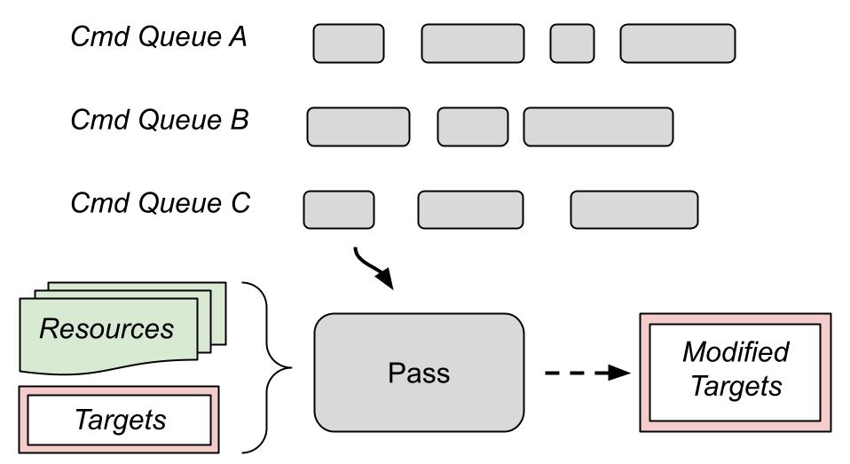
For each render pass the programmer declares what resources will be used as shader input, render targets and depth-stencils (more details on this in the Composition and workflow section). This is a big advantage as we can deduce the resource transitions that each pass requires.
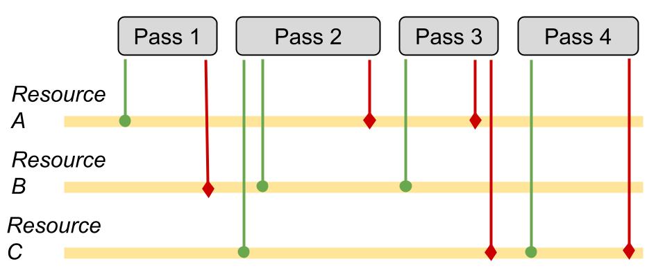
The image above shows a visual example of resource usage: green lines are read operations and red lines are write operations on different resources for each render pass.
Since the render graph has knowledge of these interactions, it can also figure out the placing of barriers for resource transitions.
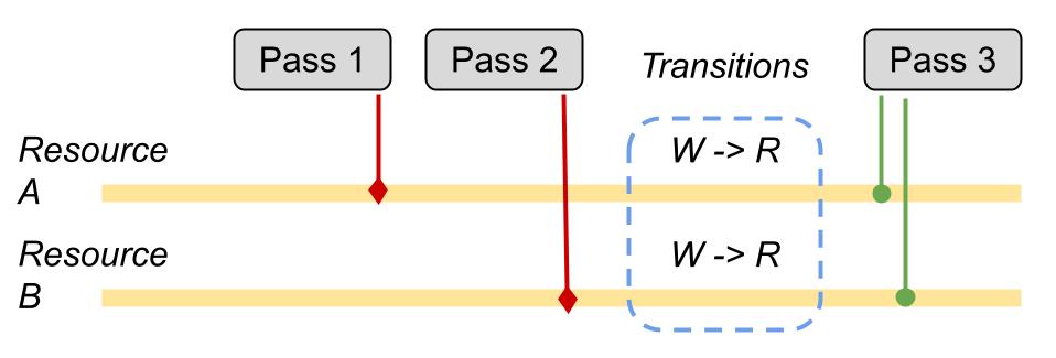
Detecting the optimal barrier configuration on a single command queue is quite trivial: if a resource A is used as shader resource for pass 1 but as a render target for pass 2, then we will need a resource transition to render target between the two passes. If both pass 1 and 2 use resource A as a shader resource, then there is no need to perform any transition.
In general, the more we can group resource transitions in a single call, the less calls to the SDK and the faster our program will perform.
Let’s take the example of a shadow mapping algorithm: we will have a graphics pass that computes a depth buffer, then a per-pixel compute pass that uses that depth information to output a shadow buffer, and finally another graphics pass that uses both the depth buffer and shadow buffer as input.
In this case, the transition of both depth buffer and shadow buffer can (and should) be grouped together when they are about to get used as shader resources for the last pass.
We can batch (group) resource barriers even if used resources are coming from different command queues.
In the case of a tripleA engine for example, it is common to have at least 3 command queues: a graphics, a compute and a copy one.
The graphics command list is meant to be the “main” queue, and in general all the queues will need synchronization mechanisms (specifically GPU fences in D3D12) to communicate with each other.
The optimization of resource transitions between different command queues can become complicated depending on the interaction between passes and how many different queues we are using.
Pavlo Muratov in his blog post explains the difficulties of making these operations fully automatic and lists the approaches we can take when dealing with an indefinite number of queues. In general it looks like the better option is grouping resource transitions and executing them on a single queue.
Manage And Optimize Resource Memory
Since each pass declares which resources are needed, it is also possible to control the lifetime of resources: allocations are also handled by the graph.
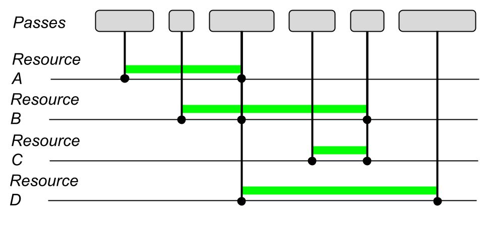
In the image above, for example, resource A is used only up to the third pass. On the other hand, resource C starts getting used in the fourth pass, and so its lifetime does not overlap the one of resource A, meaning that we can use the same memory for both resources.
The same concept applies for resource A and D, and in general we will have multiple ways to overlap our memory allocations, so we will also need clever ways to detect the best allocation strategy.
There will be resources which will be used on a per-frame basis: these are commonly called graph or transient resources and their lifetime can be fully handled by the render graph.
An example is the camera depth or the Gbuffers in a deferred lighting pass, as they will be computed on a per-frame basis.
There are then other resources, such as the window swapchain back buffer, whose lifetime is dependent on systems outside the graph, and so the graph will limit itself to just manage their state. These are known as external resources.
Transient Resource System
Since all the resources created within the RenderGraph are meant to last for a specific time span within a single frame, there is a high potential for memory re-use.
These resources, owned by the render graph and lasting a maximum of one frame, are also called transient resources.
The resource lifetime is then used to apply resource aliasing on placed resources (by strictly using D3D12 terminology).
I have talked about placed resources and resource aliasing in my previous article about Resource Handling in D3D12.
Placed resources are faster to allocate and remove compared to reserved resources since they reside on an already created GPU memory heap.
Along with them, we often find the concept of resource aliasing, which consists of using the same GPU memory for different resources whose lifetime don’t overlap during frame computation.
More details about placed resources and aliasing in the Available D3D Tools chapter.
Regarding buffers containing per-object data (and not images), this system is not necessary due to the small size that is being taken per frame, and we can use a linear allocator.
For textures the situation is different, since they take most of the used GPU memory, and so we can use strategies of resource aliasing with them.
I will further explain resource aliang in the Available Direct3D Tools section.
If we are interested in optimizing performance, a blog post by Pavlo Muratorv explains an algorithm to find the optimal scheduling for aliased resources in a render graph.
Parallel Command List Recording
As mentioned before, having a render graph also helps handling pass connections between different command queues running at the same time.
The most common case is having a Graphics + Async Compute command queues configuration.
The command to run a compute pass asynchronously should be just a matter of calling
MyGraphBuilder::ExecuteNextAsync();
just before the pass definition. The graph then will take this information to kick off the next pass on the parallel compute queue instead of using the graphics one.
For an even smarter graph, this option can be decided by inspecting the flow structure.
We could make the graph automatically handle async compute operations but turns out this is not optimal and manual settings are preferred.
For every pass that we run asynchronously, we need to make sure that resource lifetime will last up until the pass output will be used again on the main render thread.
All these mechanics are handled using GPU fences, as we are essentially synchronizing different thread executions. The tricky part will consist in finding the best approach to minimize the number of such syncing points, as they have a timing cost.
You can find more information about D3D12 command queues synchronization in the official documentation.
Composition And Workflow
I briefly talked about the render graph used by UE4 in a previous blog post about its shaders, and how it works.
A render graph uses a Retained Mode Model, which consists in first gathering all the information to render a frame, then optimize the workflow and finally render the result.
This directly opposes “Immediate Mode” where elements get rendered as they get first considered. Despite immediate mode being the most straightforward to implement, the use of retained mode allows much more optimization.
We can identify 3 steps when using a render graph:
- Setup phase: declares which render passes will exist and what resources will be accessed by them.
- Compile phase: figure out resources lifetime and make resource allocations accordingly.
- Execute phase: all the graph nodes get executed.
Frostbite Frame Graph gets built from scratch on every frame and it has a code-driven architecture. It was a conscious choice to allow more flexibility, e.g. removing/adding passes upon need.
We do not really need to build the entire graph on every frame, as discussed in apoorvaj.io, but only when the graph changes. A strategy can be computing a hash for the declared combination of passes just after the setup phase. In the next frame, if the new computed hash is the same as the one computed in the previous frame, we will reuse the already computed graph, otherwise we are going to build a new one.
Note: we could even decide to make the graph static, in a system that runs the graph setup only once, and rebuild it only if explicitly requested, if we are sure that our system will almost always need all the declared passes.
To build a graph we can use a GraphBuilder type object, from which we can statically retrieve an instance used to push all the render passes.
GraphBuilder::Get().AddPass(
“MyPassName”,
Flags,
MyPassParameters,
[MyPassParameters](){
	/* My lambda function body where we will use the PassParameters (and possibly other information) to send dispatch or draw commands */
} );
Each pass will be created from:
- Name
- Flags (e.g. if the pass is to be considered a graphics or compute one)
- Pass parameters: used to understand the needed resource transitions, lifetimes and aliasing.
- Execution lambda: where we are still going to capture the parameters just declared to use them on the drawing or dispatch commands.
The PassParameters will need to distinguish between at least shader resources and render targets in order to detect proper transitions.
struct MyPassParameterStruct{
	std::vector<ResourceRef> ShaderResources;
	std::vector<ResourceRef> RenderTargets;
}
These render passes can be further organized into Render Features, groups of passes that define a specific effect applied to the render pipeline.
Examples of render features can be Base Pass, Environment Reflections, Deferred Lighting or Shadow Maps.
It can happen that a feature resource input depends on another one, e.g. deferred lighting depends on base pass, or shadow maps depend on shadow depths.
For this reason we will also need a system to handle such dependencies.
One solution is using a map container to store output data reference of each feature: the dependent pass will include the header where the output of the first pass is defined, and add its resources as dependency where needed.
// At the end of a feature an instance of this struct will be filled and inserted in the output map
struct MyFirstFeatureOutput {
	ResourceRef MyFirstOutput;
}

// …
MyFirstFeatureOutput featureOutput { outputResource };

GraphBuilder::AddFeatureOutput<MyFirstFeatureOutput>(featureOutput);

// Then in code of a pass of the dependent feature

#include “MyFirstFeature.h”

MyFirstFeatureOutput& firstFeatOutput = GraphBuilder::GetFeatureOutput<MyFirstFeatureOutput>();

MyPassParameterStruct.ShaderResources.add(firstFeatOutput.MyFirstOutput);
Another solution, like the one adopted by UE4, is retrieving resources from the graph by hashed string.
ResourceRef sceneColor = GraphBuilder::GetOrCreateResource("SceneColor");

MyPassParameterStruct.ShaderResources.add(sceneColor);
Of course this method is less safe, because we rely on knowing what string will be used for what resource in another pass.
On the other hand, this approach can be more flexible as we do not expect the output of a specifc pass, but just a named resource which, if not used before, will be created on the spot.
Setup Phase
In the setup phase the system will go through all the defined render passes and check all the declared resources. Each declared resource will have a flag associated for its usage type, e.g.
Read, Write, ComputeRW, Render Target, DepthStencil
and also communicate the graph when we want to allocate new graph resources, e.g.
TextureRef MyGraphBuilder::CreateTexture(const TextureDesc& Desc, const char* Name, TextureFlags Flags);
Referenced (or created) resources can specify TextureFlags such as Clear, if we want to fill the texels with a certain value before use in a pass, in order to avoid reading garbage data.
The CPU memory of these resources will be guaranteed only for the execution of the pass and at the end of it (both CPU and GPU) the memory will be considered re-usable for the next frames.
Regarding render target resources, whenever we execute a write on one of them, we will need to invalidate all its previous references in the graph, in order to avoid having passes executing after the current one, and thinking of using the previous state of the resource.
This can be achieved by assigning a different internal update index to the resource, so it can be checked for validity at runtime.
Aside from resources which lifetime is tied to the execution of the graph, we can also reference external resources, the ones created from external systems (because used in different ways or also needed for other sides of the engine)
BufferRef MyGraphBuilder::RegisterExternalBuffer(const PooledBuffer& ExternalPooledBuffer, BufferFlags Flags);
In such cases the resource will be tracked by the graph, executing state transitions when needed.
An example of an external resource is the window swap chain backbuffer of Windows API.
Usually we can rely on the order of which passes get registered for the graph, to have a reliable timeline for pass execution on a single command queue. As a reminder, commands sent to a single command queue are guaranteed to get executed in the order we send them.
Further Optimization
Graph resources can be created with lazy initialization, so creating them within graph setup but allocating them only before the first pass that needs them.
The system can also deduce the state of used resources, e.g. a texture bound as a resource for a pixel shader can be deduced as read state, otherwise specified (like if we want to use it with an unordered access view).
It is also possible to deduce creation of a resource from a pass input, for example deducing the size and attributes when creating a mipmapped texture from an input buffer image.
Compile Phase
The compile phase is completely autonomous and a “non-programmable” stage, in the sense that the render pass programmer does not have influence on it.
In this phase the graph gets inspected to find all the possible flow optimizations, it will:
- Exclude unreferenced but defined resources and passes: if we want to draw a second debug view of the scene, we might be interested to draw only certain passes for it.
- Compute and handle used resources lifetime
- Resources Allocation
- Build optimized resource transition graph
For optimized resource transitions, in D3D12 we have the ID3D12GraphicsCommandList::ResourceBarrier method intended here for the specific case of D3D12_RESOURCE_TRANSITION_BARRIER.
With this concept in mind we can build an internal subsystem that handles resource transitions for us. A very basic example (still without using a render graph) can be found in the section Resource State Tracking of Learning DirectX 12 - Part3 by 3dgep.com, and so here will not be discussed.
When more than one command queue is running, the situation adds a layer of complexity.
Build Cross-Queues Synchronization
As you may already know, render operations in the same command queue are executed sequentially, but in the case that we are using multiple command queues, they will run in parallel, and so we need synchronization mechanisms to prevent race conditions on shared resources.
The less fencing we use, the faster our render operations will be, and the compile phase is a good place to insert an algorithm to minimize the wait between two or more queues.
Note: Unreal Engine, and also Frostbite when presented render graphs in 2017, do not compute the minimal amount of fences, and put manual fences where they want to optimize workflow or when needed in special cases, because in a real tripleA engine scenario, there are many hidden edge cases that might make a single algorithm to be impractical to maintain.
Pavlo Muratov in his blog article explains an idea on how to compute automatic optimal fences between parallel command queues.
One of the main concepts presented is the fact that in APIs such as D3D12, the graphics command queue is the only one that can transition all the possible kind of resource states, and so it can be called “the most competent” queue. For this reason, it is proven to be better to execute all the resource transitions on a single (graphics) queue, after proper synchronization.
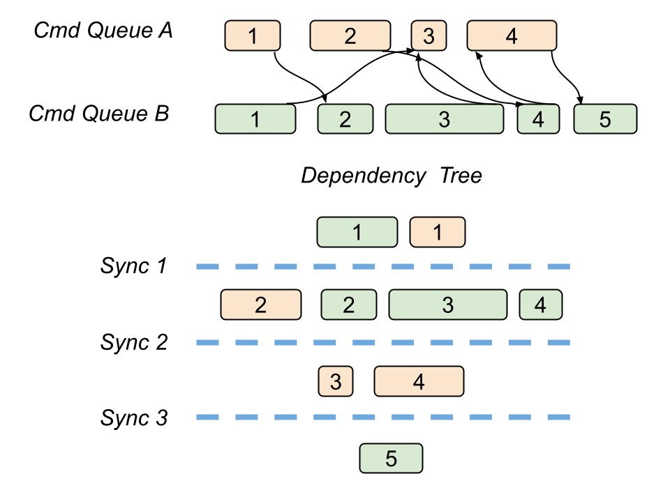
In his article, Pavlo describes how to build a dependency tree starting from an acyclic graph of render passes, which we have after we lay down every pass from the dependent queues.
Each level of a dependency tree, called dependency level, will contain passes independent of each other, in the sense of their resource usage.
By doing that we can ensure that every pass in the same dependency level can potentially run asynchronously. We can still have cases of multiple passes belonging to the same queue in the same dependency level, but this does not bother us.
As a consequence, we can put a synchronization point with a GPU fence at the end of every dependency level: this will execute the needed resource transitions, for Every queue on a single graphics command list.
This approach of course does not come for free, since using fences and syncing different command queues has a time cost.
In addition to that, it will not always be the optimal and smallest amount of synchronizations, but it will produce acceptable performance and it should cover all the possible edge cases.
Note: In real use cases, the amount of parallelization we can achieve depends on the current hardware (which many details are hidden from the programmer) and also may vary depending on how much workload we have for each pass.
Execute Phase
Execution phase is as simple as navigating through all the passes that survived the compile phase culling and executing the draw and dispatch commands on the list.
Up until the execute phase all the resources were handled by opaque and abstract references, while at execute phase we access the real GPU API resources and set them in the pipeline.
The preparation of command lists, on the CPU side, can be potentially parallelized quite a lot: in most of the cases, each pass command list setup is independent from each other.
Aside from that, command list submissions on a single command queue is not thread safe, and in any case we would first need to determine if adding parallelization would bring significant gains.
Available Direct3D Tools
Submit Command Lists
We can submit multiple command lists at the same time by using ID3D12CommandQueue::ExecuteCommandLists method.
For example, if we build a pass dependency tree first, where each layer contains independent passes.
We can put every pass on the same “dependency layer” on a different command list, and then execute all together with the same ExecuteCommandLists call.
The trick here is that we will never be sure how much of these operations will be actually made parallel on GPU. The documentation itself specifies that the work of a second list “may start” before the end of the first one of the batch, but we will never know for sure, as these are hardware-dependent details!
What we know for sure is that in the case we need to submit multiple command lists, we will spare the CPU workload of submitting them singularly.
Placed Resources
Since creating Committed resources, and so having an independent resource heap for each of them, would use ton of memory, the straightforward solution to it is to use Placed Resources.
They are called “placed” because they will be allocated linearly in a pre-existing, and ideally permanent, GPU memory heap. This characteristic makes them the fastest and most flexible type or resource to handle, which was not available in Direct3D11.
We can create them by calling ID3D12Device::CreatePlacedResource which asks for an already existing heap and offset, plus details about the resource we want to allocate.
When handling placed resources, we can operate memory aliasing with them, which is described next.
Aliased Resources
The fundamental concept for aliased resources is if, during the render timeline, two resources have a usage (and so a lifetime) that does not overlap, then they can use the same memory.
Note: Aliasied resources can spare more than 50% of the used resource allocation space, especially when using a render graph. They add an additional managing resource complexity to the scene, but if we want to spare memory, they are almost always worth it.
We can also alias reserved resources, also known as tiled resources, but this goes beyond the scope of this article.
For the simple model usage of aliased resources, we say that an aliased resource is** active, when the shared memory is currently assigned for such resource use. In the meantime, all the other resources that share memory with the previous one, will be considered **inactive, and so not meant to be used.
It is considered invalid for a GPU to read or write on an inactive resource and placed resources are created in an inactive state.
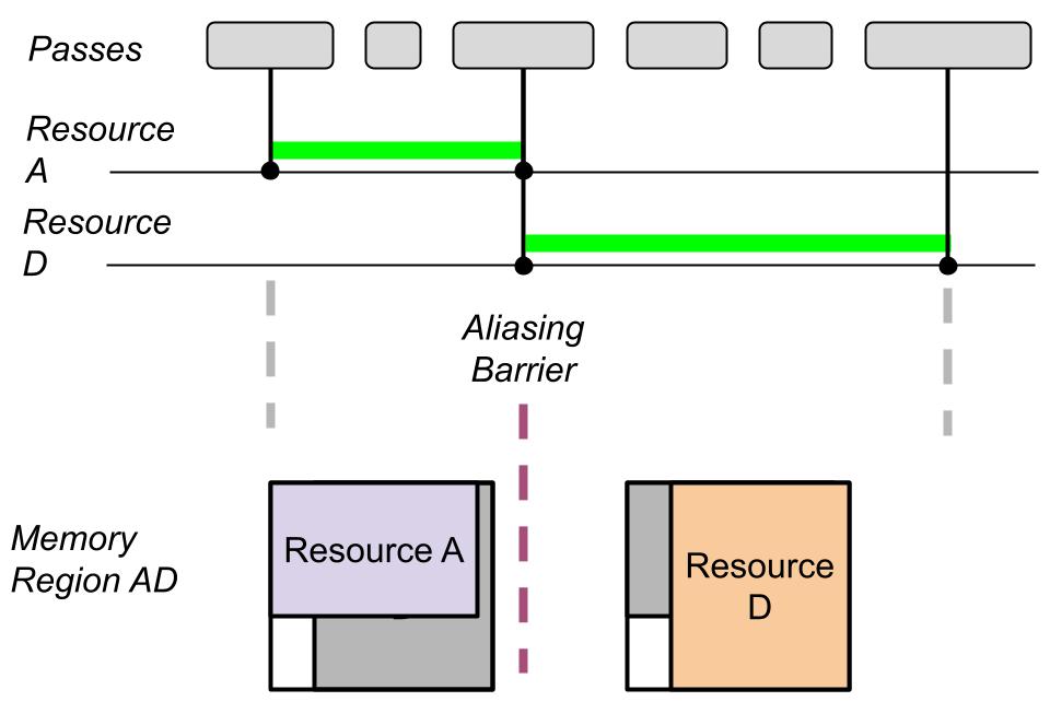
Between the usage of two overlapping aliased resources we always need an aliasing barrier.
They are defined by the D3D12_RESOURCE_ALIASING_BARRIER structure.
Using them is similar to resource transition barriers except they are made for aliased resources.
When we are dealing with aliasing resources, regular resource barriers are no longer useful since they would refer to a place of memory shared by multiple resources.
D3D12_RESOURCE_ALIASING_BARRIER myAliasingBarrier{
prevResource.Get(), resourceToActivate.Get()};
myCmdList->ResourceBarrier(1, &myAliasingBarrier);
The aliasing barrier takes as arguments the resource that existed before aliasing and the resource that will become the active resource after the barrier.
The before resource can be left NULL, and in that case all the resources that shared memory with the after resource, will become inactive.
It is possible to batch aliasing barriers with other transition barriers and we should do it to achieve best performance.
As explained in a blog post by Adam Sawiki, there is an important detail concerning resources created with D3D12_RESOURCE_FLAG_ALLOW_RENDER_TARGET or D3D12_RESOURCE_FLAG_ALLOW_DEPTH_STENCIL from D3D12_RESOURCE_FLAGS enumeration.
Render targets and depth stencils get handled differently by the GPU, compared to shader resources such as textures, and they need additional care when used in resource aliasing.
Specifically, every time they become the active aliased resources, and so after an aliasing barrier that sees them as after resources, they need to be initialized with one of the following operations:
- A Clear operation: like ClearRenderTargetView or ClearDepthStencilView which will fill the current resource with a specified value, such as 1 or 0 or a defined color. A clear comes handy when the next render operations will be changing just a subset of the current resource data, and we need the remaining to contain valid information. Examples include filling a render target with blue color before drawing a cube into it.
- A DiscardResource operation: a very quick operation that updates just the resource metadata by informing that the current content does not need to be preserved. DiscardResource is the preferred choice when the next operation is going to compute every texel of our resource.
- A Copy operation: such as CopyBufferRegion, CopyTextureRegion, or CopyResource will copy the content of another resource into the current one.
Note: For non-render targets and non-depth-stencil the initialization condition is not mandatory, and we are free to read garbage data from them!
We can also use aliased resources with an advanced use semantic, explained in the official docs, to get the best performance in specific situations.
With advanced use we can forget about resource active and inactive states, and access subregions of overlapping resources at any time, as long as the following rules are satisfied:
- We still need an aliasing barrier between two different GPU resource accesses on the same memory subregion.
- We still need subregion initialization for render targets and depth-stencils like it was happening in the simple model.
Advices
Fences Are Expensive
Fences in a render graph are mainly used to synchronize the access of resources, especially when shared between two command queues (e.g. graphics + compute).
Using them finely grained for each resource is bad: we should signal a fence to sync as many resource usages as possible.
As mentioned in previous sections, it is possible to build a deferred barrier system, where barriers are appended to a list and wait up until necessary before flushing the list. With a single command queue this system is quite straightforward but with multiple queues it can become complex very quickly, as already explained in the Compile Phase section.
Use Resource Shader Visibility
Shader visibility is a parameter of D3D12_ROOT_PARAMETER structure that will be used as input for the root signature.
By declaring the right shader visibility on resource views and samplers, since the graphics drivers can optimize their usage.
This should come along with the render graph functionalities: since the graph has the full list of passes on which a specific resource will be used and in which ways, it is also possible to decide the proper shader visibility.
Do not use SHADER_VISIBILITY_ALL as it is the less optimized entry.
Modify Root Signatures and PSOs is Expensive
Cache root signatures and PSOs as much as possible, and reduce changes to such objects to the minimum.
You can read more about PSO and Root Signature in my previous articles:Pipeline State Object and Root Signature.
Caching PSOs can restrict the range of possible operations on a material: changing depth bias, viewport, scissor rect, rasterizer or any other part of the PSO would invalidate cache and so we cannot allow these operations to be done per frame anymore.
In the case of depth bias for example, we can solve this issue by considering the bias inside the pixel shader instead of using the PSO parameter.
PSO cache can take memory, and we can potentially have a high number of different PSOs for each material permutation, but this is an acceptable cost to gain runtime performance.
Descriptor tables can be built from shader parameters groups that do not change frequently. An example are static descriptors for a material shader parameter group: we can first build a root table entry referencing them, then reference the same root table entry every time we need to use such material.
Sources
-
Holger Gruen - DirectX™ 12 Case Studies
https://developer.download.nvidia.com/assets/gameworks/downloads/regular/GDC17/DX12CaseStudies_GDC2017_FINAL.pdf -
Yuriy O’Donnell - FrameGraph in Frostbite
https://www.gdcvault.com/play/1024612/FrameGraph-Extensible-Rendering-Architecture-in -
Tiago Rodrigues - Moving To DirectX 12
https://www.gdcvault.com/play/1024656/Advanced-Graphics-Tech-Moving-to -
Our Machinery - High-Level Rendering Using Render Graphs
https://ourmachinery.com/post/high-level-rendering-using-render-graphs/ -
Graham Wihlidal - Halcyon: Rapid Innovation using Modern Graphics
https://media.contentapi.ea.com/content/dam/ea/seed/presentations/wihlidal2019-rebootdevelopblue-halcyon-rapid-innovation.pdf -
Apoorva Joshi - Render Graphs
https://apoorvaj.io/render-graphs-1/ -
Pavlo Muratov - Organizing GPU Work with Directed Acyclic Graphs
https://levelup.gitconnected.com/organizing-gpu-work-with-directed-acyclic-graphs-f3fd5f2c2af3 -
Pavlo Muratov - GPU Memory Aliasing
https://levelup.gitconnected.com/gpu-memory-aliasing-45933681a15e -
Adam Sawicki - Initializing DX12 Textures After Allocation and Aliasing
https://asawicki.info/news_1724_initializing_dx12_textures_after_allocation_and_aliasing -
Microsoft - Memory Aliasing and Data Inheritance
https://docs.microsoft.com/en-us/windows/win32/direct3d12/memory-aliasing-and-data-inheritance -
Microsoft - ID3D12Device::CreatePlacedResource
https://docs.microsoft.com/en-us/windows/win32/api/d3d12/nf-d3d12-id3d12device-createplacedresource -
Microsoft - Using Resource Barriers
https://docs.microsoft.com/en-us/windows/win32/direct3d12/using-resource-barriers-to-synchronize-resource-states-in-direct3d-12